
Download Well Sketch 1.0 – Well Construction Visualization Software
Well Sketch 1.0 is a specialized oil and gas engineering software designed for the visualization and management of well construction data. Developed to serve professionals in the Oil and Gas Industry and Geosciences, this tool is crucial for creating detailed well schematics and quantifying project resources. Its functionality assists engineers in effectively planning and executing complex well operations.
Understanding Well Sketch 1.0 and Its Applications
Overview of Well Sketch Software
Well Sketch 1.0 functions as a critical application for visualizing well constructions and managing associated data within the oil and gas sector. It enables users to create precise graphical representations of wellbore information, which is fundamental for operational planning, resource quantification, and project documentation. The software supports various data inputs to facilitate a comprehensive understanding of well structures.
Features and Capabilities of Well Sketch 1.0
Multiple Well Column Types
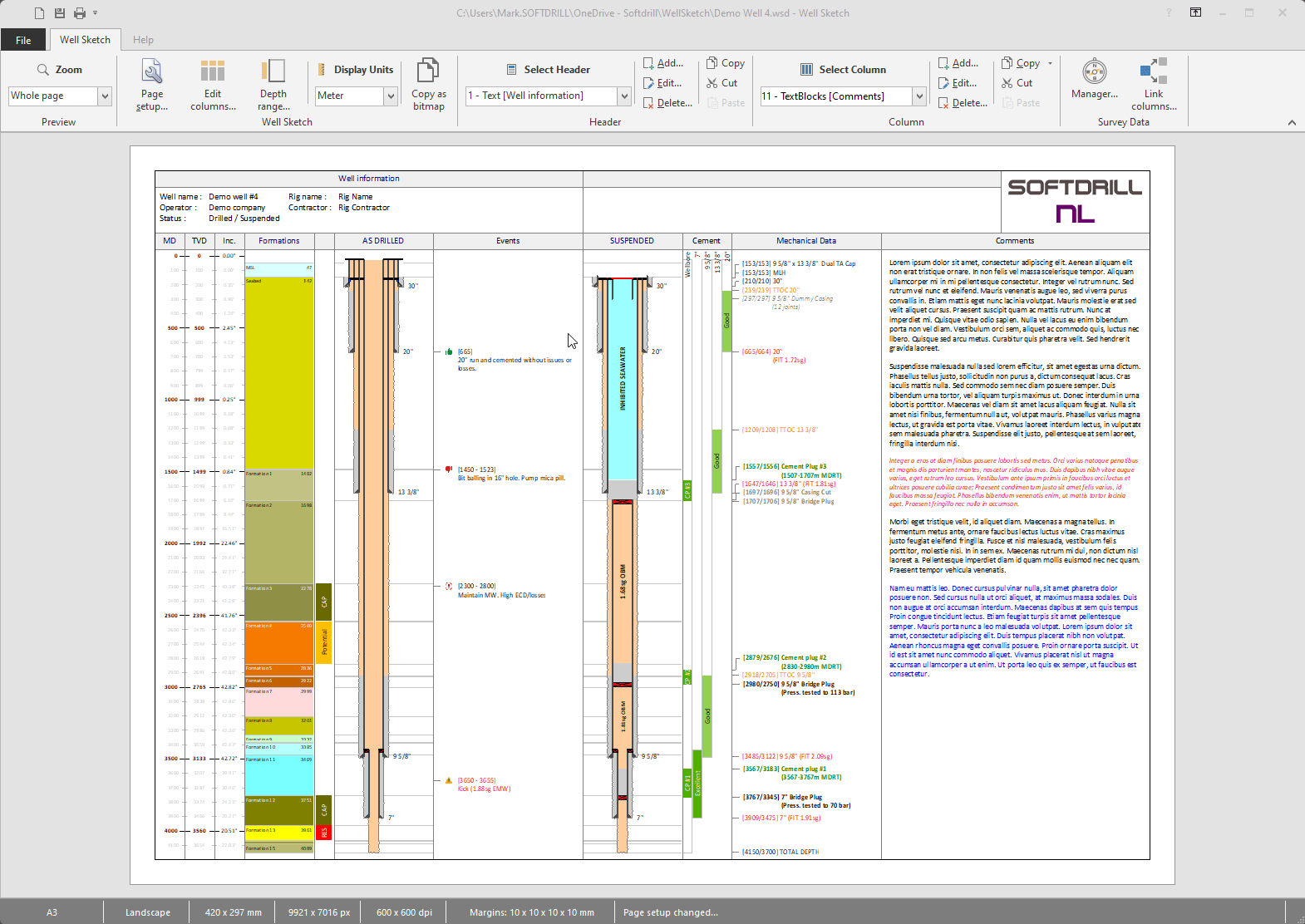
Well Sketch 1.0 supports the drawing and management of diverse well column types. This variety allows for detailed and context-specific representation of subsurface information crucial for engineering analysis and decision-making. Key column types include:
- Axis: Establishes the primary reference line for the wellbore.
- Formations: Depicts geological layers encountered during drilling.
- Well Schematics: Visualizes the casing, tubing, and other structural components of the well.
- Cement Evaluation: Represents data related to the cement job performed in the wellbore.
- Annotations: Allows for the addition of descriptive text and labels to clarify specific features.
Linking Survey Data for Enhanced Accuracy
The software facilitates accurate calculations and visualizations by enabling users to link well columns directly to survey data. This feature is essential for engineering tasks that require precise measurements. By integrating survey data, Well Sketch 1.0 can accurately compute Total Vertical Depth (TVD) and inclination, providing a reliable foundation for subsequent analysis and planning.
Flexible Printing Options for Well Drawings
Well Sketch 1.0 offers versatile printing capabilities to accommodate various documentation and presentation needs. Users can configure print settings to match different paper sizes, from standard A4 to large-format Arch E. Options for scaling drawings to fit the page or specifying exact dimensions ensure that generated well schematics are ready for inclusion in project reports, client presentations, or operational manuals.
Real-World Applications in Oil and Gas Engineering
In practical oil and gas engineering workflows, Well Sketch 1.0 serves as an indispensable tool for visualizing and analyzing well construction data. Engineers leverage its capabilities for detailed project planning, including the accurate representation of casing programs, formation tops, and cementation stages. The ability to link survey data allows for precise depth calculations, which are critical for safety and operational efficiency during drilling and completion phases. Furthermore, the schematic drawings generated can be used for clear communication among project teams and for post-operational analysis and historical record-keeping.
Comparative Insight: Well Sketch vs. Other Industry Tools
Compared to generic CAD software, Well Sketch 1.0 is specifically tailored for the intricacies of well construction visualization in the oil and gas industry. While broader design tools may offer drawing functionalities, Well Sketch integrates specialized features such as linked survey data for TVD calculations and pre-defined column types for geological formations and well components. This focus allows for more efficient and accurate data representation relevant to geosciences and well engineering compared to general-purpose schematic software.
Future Developments and Upcoming Features
While specific future plans for Well Sketch 1.0 require direct developer input, industry trends suggest potential enhancements. Future development may include expanded support for advanced data formats, improved integration with real-time drilling data streams, and more sophisticated analytical tools for formation evaluation. User feedback and evolving industry standards will likely influence the introduction of new visualization options and project management features to further streamline well construction workflows.
Frequently Asked Questions
What types of columns can be drawn using Well Sketch 1.0?
Well Sketch 1.0 allows users to draw various well column types, including Axis, Formations, Well Schematics, Cement Evaluation, and more, enabling versatile data representation for comprehensive well analysis and documentation.
Can Well Sketch 1.0 link data from surveys?
Yes, Well Sketch 1.0 features a survey manager that allows users to link well columns to survey data for accurate calculations of total vertical depth (TVD) and other critical directional metrics essential for wellbore integrity and planning.
How can I print well drawings created in Well Sketch 1.0?
Users can configure Well Sketch 1.0 to print drawings in various paper sizes, including A4 and Arch E, with options for scaling to fit or precise size adjustments as needed, ensuring clear and adaptable documentation output.


Reviews
There are no reviews yet.