

Ensoft LPILE 2026.13.04 – Internationally Recognized Software for Laterally Loaded Pile Analysis Using the p‑y Method
LPILE is a special‑purpose and internationally recognized computer program based on rational procedures for analyzing a pile under lateral loading using the p‑y method . The program solves the differential equation for a beam‑column using a finite difference approach, computing deflection, bending moment, shear force, and soil response over the length of the pile .
With its first release dating back to 1986, LPILE has continuously been developed and improved to meet user needs and incorporate state‑of‑the‑art literature and procedures . Nonlinear lateral load‑transfer from the foundation to the soil is modeled using p‑y curves generated internally using published recommendations for various types of soils and rocks, or user‑inputted p‑y curves . Specialized procedures are also available for computing p‑y curves for layered soils and rocks .
Version 2026.13.04 is the latest release in LPILE’s 2026 development cycle. Ensoft’s version numbering follows the format: Year.DataFormat.Revision . This version continues to incorporate state‑of‑the‑art analysis procedures including advanced structural models, LRFD capabilities, and comprehensive visualization tools
Primary Users
LPILE 2026.13.04 is designed for geotechnical engineers, structural engineers, and foundation design specialists who need to analyze the response of piles and drilled shafts subjected to lateral loading. It serves professionals who:
-
Design deep foundations for bridges, buildings, offshore structures, and transmission towers where lateral loads from wind, earthquakes, waves, or earth pressures are critical
-
Evaluate pile performance under combined axial and lateral loads using the internationally recognized p‑y method
-
Perform push‑over analyses and buckling assessments for piles in complex soil conditions
-
Conduct seismic analyses including liquefaction effects and soil movement profiles
-
Generate foundation stiffness matrices for integration into overall structural models
Key Features & Capabilities
Core Analysis Methods
-
Finite Difference Solution: Solves the beam‑column differential equation for lateral pile response with nonlinear soil springs
-
p‑y Curve Method: Nonlinear lateral load‑transfer using internally generated curves for various soil types (clay, sand, liquefied sand, weak rock, massive rock) or user‑defined curves
-
p‑y Criteria: Includes models for soft clay (Matlock), stiff clay (Reese), sand (API, O’Neil), liquefied sand (Franke & Rollins), and rock (Liang et al.)
-
Multiple Analysis Modes: Conventional analysis, LRFD analysis, nonlinear EI‑only mode, push‑over analysis, and pile buckling analysis
Structural Modeling
-
Pile Sections: Wide‑flange (AISC library), circular (hollow/full), rectangular, and user‑defined sections
-
Nonlinear Moment‑Curvature: Automatic generation of nonlinear moment‑curvature relationships for reinforced concrete sections
-
Confinement Effects: Mander, Priestley, and Park (1998) model for confined concrete in rectangular and circular shafts
-
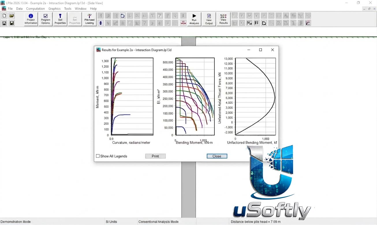
Interaction Diagrams: Automatic generation of full interaction diagrams for all sections
-
Reinforcement Definition: User‑defined bar areas, hollow bars, and pipes
Loading and Boundary Conditions
-
Pile‑Head Conditions: Five types including free‑head, fixed‑head, and elastically restrained conditions
-
Loading Types: Static loading, cyclic loading, distributed lateral loads, and soil movement profiles
-
Soil Movement Modeling: Input profiles for slope instability, lateral spreading, liquefaction, and seepage
-
Multiple Load Cases: Up to 100 load combinations for LRFD analyses
Advanced Capabilities
-
Push‑Over Analysis: Automatic push‑over analyses using free‑head or fixed‑head conditions for a range of pile‑head displacements
-
Pile Buckling Analysis: Automatic buckling analysis with various pile‑head fixity conditions
-
LRFD Implementation: Up to 100 load combinations with resistance factors for flexure and shear
-
Stiffness Matrix Computation: Pile‑head stiffness matrix values for soil‑structure interaction studies
-
Pile‑Head Stacking Graphs: Graphical display of displaced pile heads for different pile lengths to aid in optimal insertion calculations
Output and Visualization
-
Graphical Results: Deflection, bending moment, shear force, and soil response vs. depth
-
p‑y Curve Plots: Generated at user‑specified depths for review
-
Load Test Data Comparison: Import and compare computed results to field load test data
-
Export to Excel: Direct export of plots with pre‑formatted tabs for numerical values and graphs
-
Report Generation: Formatted text output with summary tables and detailed results






Reviews
There are no reviews yet.