
Download NI Circuit Design Pro Suite 14.3 – End-to-End SPICE Simulation & PCB Layout
NI Circuit Design Pro Suite 14.3, developed by National Instruments (an Emerson subsidiary), is a comprehensive electronic design automation (EDA) software package. It integrates advanced schematic capture and SPICE simulation capabilities through NI Multisim Pro with professional PCB layout design via NI Ultiboard Pro. This powerful suite is tailored for electrical and electronics engineers, academic laboratories, and R&D departments engaged in developing complex electronic systems.
Unified Electronic Design Platform
NI Circuit Design Pro Suite 14.3 represents the fusion of NI Multisim Pro and NI Ultiboard Pro, offering a cohesive environment for electronic circuit development. Originating from the integration of Multisim (formerly Electronics Workbench) and Ultiboard (formerly ULTIboard) under National Instruments in 1999, this suite provides a streamlined workflow. The unified platform eliminates the need for manual data transfer between schematic design and PCB layout, significantly reducing errors and accelerating the design cycle.
High-Precision SPICE Simulation with Multisim Pro
Original Berkeley SPICE Core
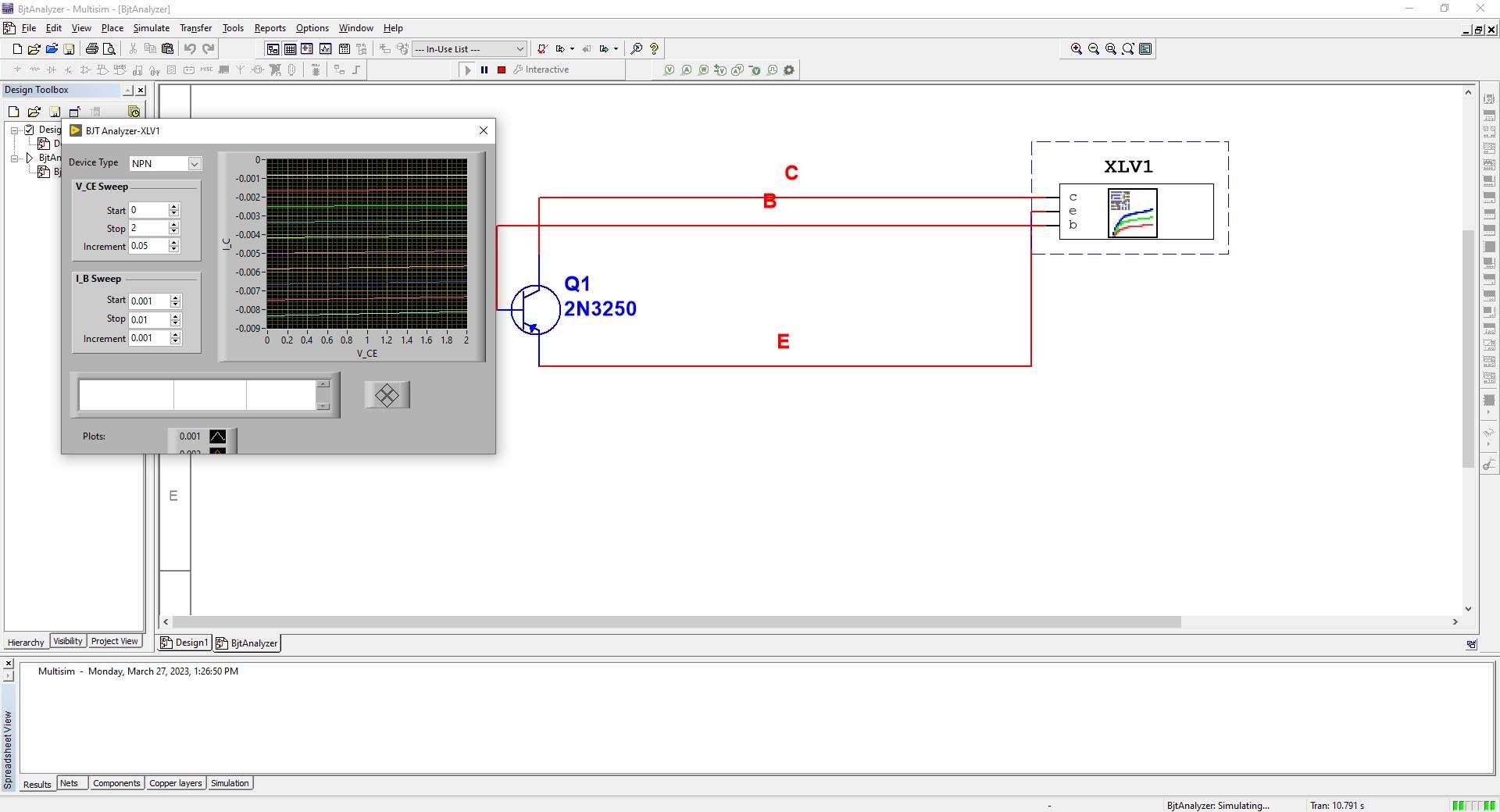
At the heart of NI Multisim Pro lies the original Berkeley SPICE engine, ensuring high accuracy and reliability for analog, digital, and mixed-signal circuit simulations. This foundational technology supports enhanced convergence algorithms, allowing engineers to reliably analyze complex circuits with greater precision and fewer simulation errors.
Advanced Analysis & Virtual Instruments
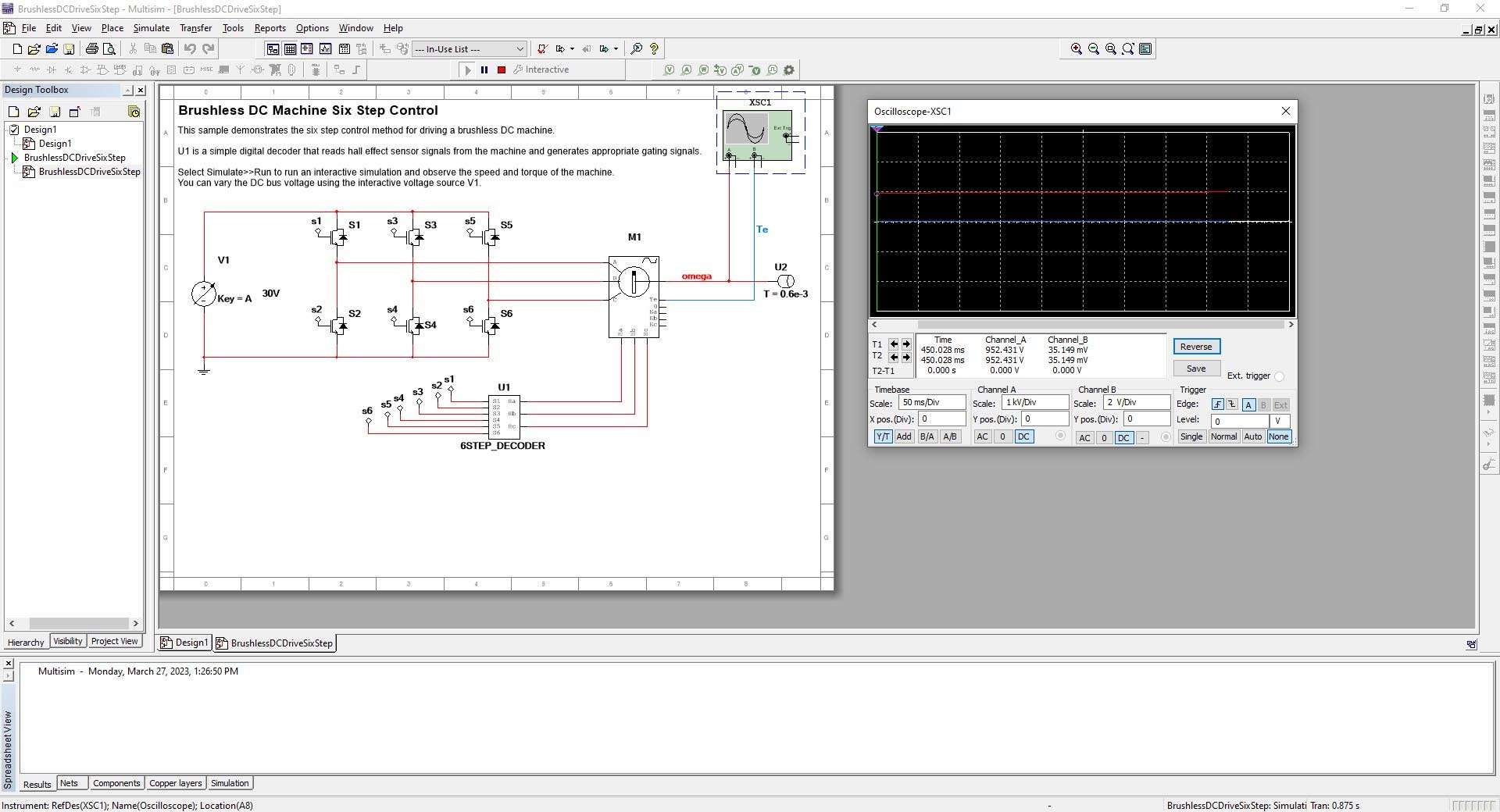
Multisim Pro equips engineers with a suite of advanced simulation and analysis tools. Beyond standard DC operating point and transient analyses, it features sophisticated options like Fourier analysis for spectral content, Monte Carlo simulations for statistical analysis, and worst-case analysis. Furthermore, integrated virtual instruments, including an oscilloscope, logic analyzer, and spectrum analyzer, provide an interactive debugging environment that mirrors real-world lab equipment, facilitating efficient circuit validation.
Professional PCB Layout in Ultiboard Pro
Real-Time Design-Rule Checking
NI Ultiboard Pro features an advanced real-time design-rule checking (DRC) system that operates interactively during the layout process. This enables engineers to detect and correct potential manufacturing violations, such as spacing or connectivity issues, as they place components and route traces. The system supports customizable net class constraints, ensuring that critical nets meet specific design requirements.
Multi-Layer & 3D Visualization
The software offers robust capabilities for designing complex multi-layer printed circuit boards (PCBs). Ultiboard Pro supports an extensive number of layers, detailed layer stack management, and flexible via options, including blind and buried vias. Its integrated 3D visualization engine allows for real-time clearance checks and a more intuitive understanding of the board’s physical construction, aiding in the design of high-density boards and preventing mechanical conflicts.
Schematic-to-PCB Workflow Automation
NI Circuit Design Pro Suite 14.3 automates critical data transfer steps between schematic capture and PCB layout. Forward and back annotation features ensure that changes made in either the schematic or layout environment are accurately reflected in the other, maintaining design integrity. The suite supports seamless netlist import and export, automated Bill of Materials (BOM) generation, and the output of fabrication files like Gerber and ODB++, significantly streamlining the path from design to manufacturing.
Industry Applications & Case Studies
The integrated nature and advanced capabilities of NI Circuit Design Pro Suite 14.3 make it suitable for a wide range of applications:
- Academic Laboratories: Widely utilized for teaching circuit theory, simulation, and PCB design principles due to its user-friendly interface and comprehensive feature set.
- Power Electronics Prototyping: Offers advanced simulation models and layout tools necessary for designing and validating power supplies, converters, and motor control systems.
- Mixed-Signal System Validation: The combination of accurate SPICE simulation and detailed layout features is ideal for developing and testing systems that incorporate both analog and digital components.
- High-Density PCB Fabrication: Ultiboard Pro’s multi-layer support and real-time DRC are critical for designing complex PCBs found in modern devices, including IoT applications.
What’s New in Version 14.3
- Enhanced SPICE convergence algorithms for improved simulation accuracy and stability with complex circuit topologies.
- Expanded component libraries with new power electronics models and integrated device models.
- Improved support for ODB++ file output, facilitating modern PCB manufacturing workflows.
- User interface refinements and performance optimizations for a more efficient design experience.
Frequently Asked Questions
How does the real-time SPICE simulation in Multisim Pro improve circuit validation?
Multisim Pro employs the original Berkeley SPICE engine with enhanced convergence algorithms, enabling accurate analog, digital, and mixed-signal simulations. Real-time parameter adjustments and virtual instruments, such as an oscilloscope and spectrum analyzer, allow engineers to validate and debug circuits interactively before hardware prototyping, significantly reducing the time needed for design iteration.
What PCB layout capabilities does Ultiboard Pro offer for complex multi-layer designs?
Ultiboard Pro supports up to 64 PCB layers, blind/buried vias, differential-pair routing, and real-time design-rule checking. Its 3D visualization engine and advanced editing features, including dynamic copper pours and comprehensive layer stack management, ensure precise layout control essential for high-density boards.
How does the integrated workflow between Multisim and Ultiboard streamline the design process?
The suite enables seamless schematic transfer from Multisim to Ultiboard with forward and back annotation, ensuring synchronized updates between the two domains. Automated netlist export, BOM generation, and Gerber/ODB++ output eliminate manual data handoffs, thereby reducing errors and significantly accelerating the time to PCB fabrication.


Reviews
There are no reviews yet.