Download AVEVA Diagrams 14.2 – Comprehensive Tool for P&IDs and Process Diagrams
Download AVEVA Diagrams 14.2, a specialized application developed by AVEVA Group plc for creating Piping and Instrumentation Diagrams (P&IDs), Process Flow Diagrams (PFDs), and HVAC diagrams. This software is integral to the design workflows in mechanical and manufacturing industries, specifically within process engineering for sectors such as oil and gas, shipbuilding, and industrial facilities.
Introduction to AVEVA Diagrams 14.2
Overview and History of AVEVA
AVEVA Diagrams is part of a sophisticated suite of engineering and design software solutions provided by AVEVA Group plc. The company’s origins trace back to a UK government initiative in 1967, evolving over decades into a significant force in digital transformation for industrial engineering and operations. AVEVA Diagrams itself is a product of this evolution, designed to streamline the creation and management of critical schematic documentation within the broader AVEVA software ecosystem.
Core Functionalities and Applications
Creating P&IDs and PFDs
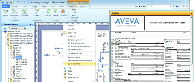
AVEVA Diagrams 14.2 provides a robust environment for drafting essential schematic diagrams. Users can efficiently generate Piping and Instrumentation Diagrams (P&IDs) to detail process piping, instrumentation, and control systems, as well as Process Flow Diagrams (PFDs) that illustrate the overall flow of materials and energy within a system. The software includes a comprehensive library of symbols and intelligent objects crucial for accurate representation.
Integration with AVEVA Software Ecosystem
A key strength of AVEVA Diagrams is its seamless integration within the AVEVA software suite. This allows for direct connection with other AVEVA applications, such as AVEVA Engineering and AVEVA PDMS. This integration facilitates real-time updates to project databases, ensuring that schematic data is always synchronized with the overall project model and design documentation, enhancing collaborative workflows.
Key Features of AVEVA Diagrams 14.2
User-Friendly Environment
The software offers an intuitive user interface designed to facilitate ease of use and efficient diagram creation. Features include drag-and-drop functionality for symbols, customizable toolbars, and straightforward symbol creation utilities. This user-friendly environment helps engineers to focus on the design rather than the intricacies of the software itself.
Data Management and Model Integration
AVEVA Diagrams excels in managing schematic data comprehensively. Diagrams created are linked to a central project database, enabling bidirectional data flow. This means changes made in the diagrams can update the database, and conversely, information from the database can be leveraged directly within the diagrams, ensuring data consistency and providing contextual information.
Real-World Use Cases and Industry Applications
Applications in Plant Design and Marine Engineering
In plant design, AVEVA Diagrams is instrumental in developing detailed schematics for process facilities, including those in the oil and gas sector. For marine engineering, it is used to create diagrams for ship systems, from piping layouts to HVAC controls. The software’s ability to manage complex data and ensure consistency makes it valuable for large-scale industrial and shipbuilding projects.
Advantages of Using AVEVA Diagrams
Consistency and Error Reduction
By leveraging automated rules and actions, AVEVA Diagrams helps in creating diagrams that adhere to predefined engineering standards. This systematic approach significantly reduces the likelihood of manual errors and ensures improved diagram consistency across projects. The software acts as a safeguard for maintaining design integrity and compliance.
Contextual Access and Decision Support
Diagrams created in AVEVA Diagrams provide quick contextual access to related engineering data within the AVEVA ecosystem. This direct link to comprehensive project information empowers engineers and designers, enabling faster, more informed decision-making throughout the design and operational lifecycle of a facility or vessel.
Frequently Asked Questions
What types of diagrams can be created using AVEVA Diagrams 14.2?
AVEVA Diagrams 14.2 allows users to create various types of engineering diagrams, including Piping and Instrumentation Diagrams (P&IDs), Process Flow Diagrams (PFDs), and HVAC diagrams. These diagrams are essential for defining functional designs in plant and marine engineering projects.
How does AVEVA Diagrams integrate with other AVEVA tools?
AVEVA Diagrams integrates seamlessly with other AVEVA products such as AVEVA Engineering and AVEVA PDMS, allowing for real-time data updates across projects. This integration enhances overall project efficiency and data consistency during design and operational phases.
How does AVEVA Diagrams help reduce errors in design?
The software includes automated rules and actions that support users in creating diagrams that adhere to predefined standards, significantly minimizing the risk of errors. This feature ensures that diagrams are consistent and compliant throughout the design process.


Reviews
There are no reviews yet.